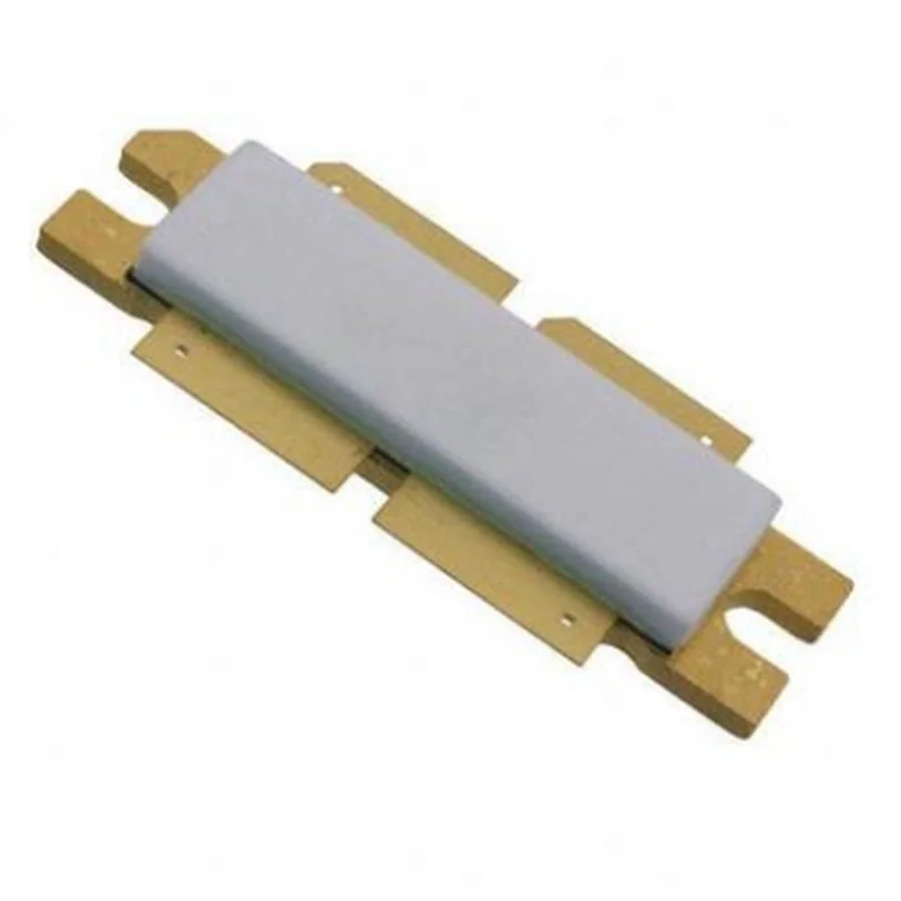
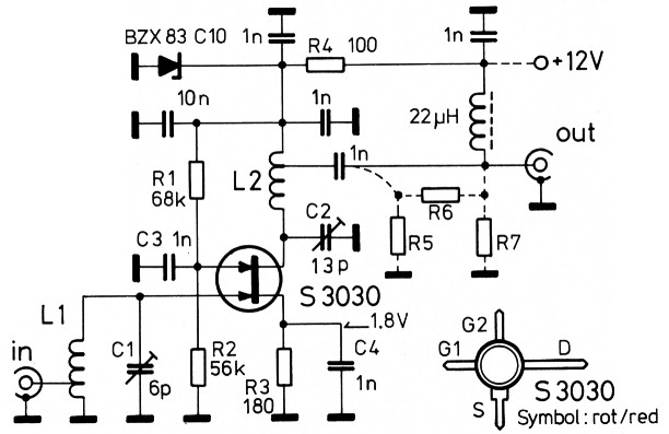
First, Gallium arsenide MESFET. MESFET is called MESFET because the Metal Semiconductor Field Effect Transistor, that's why it's called MESFET. This is the one type of the junction field effect transistor. So most junction field effect transistor, and you know the field effect means the electric field in MOSFET. Avantek AN-7714M GaAs FET Amplifier& PS-51 Power Supply- 7.25-7.75 GHz An Avantek model AN-7714M GaAs FET Amplifier mounted on a PS-51 Power Supply. AN-7714M: Frequency Range: 7.25 to 7.75 GHz, PS-51: 115VAC(includes power cord for this output) Please take a look at all of the provided photos before placing your bid to thoroughly inspect the. Explosive rapidity. Other words, almost no GaAs FET gates are insulated from The simplest of the the channels in terms of direct current. Three is the junction FET (JFET). Because of its simplicity GaAs FETs are called “normally ON” type devices, the maxi. GaAs Process is Approved for Space Applications with Proven Reliability Commercial, Industrial, Military, and Space Grade 100% Wafer Bond Pull, Die Shear, Wafer DC Burn In, and Bake Tests in Evaluation per MIL-PRF-38534 100% Die Probe Test with Data.
This invention relates to a GaAs mosfet and to a method of making a GaAs mosfet and to a mosfet when made by the method. A mosfet is a metal-oxide semiconductor field-effect transistor.
The invention accordingly provides a GaAs mosfet comprising a p-type gallium arsenide single crystal having two grooves formed therein, each groove containing a layer of indium, a layer of dopant overlying the indium and a layer of Al2 O3 overlying the dopant, each groove overlying respective n+ region of the gallium arsenide, the surface of the gallium arsenide single crystal on each side of each groove comprising native oxide to a depth contiguous to the n+ regions, the layers of dopant being in contact with the junctions between the n30 regions and the native oxides, there being provided a flat contact pad covering substantially all the native oxide between the grooves and in contact with the Al2 O3 of both grooves, a second contact pad covering the native oxide on the remaining side of one groove and in contact with the dopant via an electrically ruptured part of the Al2 O3 of that one groove, and a third contact pad covering the native oxide on the remaining side of the other groove and in contact with the dopant via an electrically ruptured part of the Al2 O3 of that other groove.
The three contact pads are preferably each of silver. The gallium arsenide single crystal may bear, on a face remote from the grooves, successive layers one of indium and one or more of metals forming ohmic contacts with the p-type gallium arsenide for example one layer of zinc and one layer of silver. The silver overlying the zinc may be connected to a contact wire and to heat sink. Usually, the native oxide under the first contact pad extends continuously from one groove to the other. The invention further provides a method of making a GaAs mosfet, the method comprising:
FORMING TWO GROOVES IN A SURFACE OF A P-TYPE GALLIUM ARSENIDE SINGLE CRYSTAL, DEPOSITING IN EACH GROOVE A LAYER OF INDIUM,
DEPOSITING OVER THE INDIUM IN EACH GROOVE A LAYER OF A DOPANT,
DEPOSITING OVER THE DOPANT A LAYER OF ALUMINIUM, ANODICALLY OXIDISING THE SURFACE OF THE WORK UNTIL ALL THE ALUMINIUM IS OXIDISED TO Al2 O3 and the gallium arsenide is oxidised to a depth contiguous to the dopant,
annealing the work to form an n+ layer in the gallium arsenide under the grooves and contiguous with the anodically oxidised gallium arsenide,
depositing contact metal simultaneously or in any order (i) covering substantially all the anodically oxidised gallium arsenide between the grooves and in contact with both of the layers of Al2 O3, (ii) covering the anodically oxidised gallium arsenide on the remaining side of one groove and in contact with the Al2 O3 of that one groove, and (iii) covering the anodically oxidised gallium arsenide on the remaining side of the other groove and in contact with the Al2 O3 of that other groove,

and rendering electrically conductive Al2 O3 between the dopant and the contact metal (ii) and (iii). The method may further comprise, before or after the annealing, depositing, on a face of the gallium arsenide single crystal remote from the grooves, a layer of indium and layer(s) of metal(s) forming ohmic contacts with the p-type gallium arsenide, for example a layer of zinc adjacent the indium and a layer of silver overlying the zinc.

The dopant may be for example germanium and is conveniently tin.
The contact metal is preferably silver. The annealing preferably lasts from 1 to 10 minutes at a temperature preferably of 300° to 650° C., preferably over 500° C., e.g. 600° C., and is performed in an atmosphere most preferably of nitrogen. Conveniently, the Al2 O3 between the dopant and the contact metal (ii) and (iii) is rendered conductive by applying thereto a voltage sufficient to break down the Al2 O3 but insufficient to break down the anodically oxidised gallium arsenide.
The indium may be deposited by evaporation, e.g. by using a photoresist float-off method. The invention also extends to a GaAs mosfet when made by the method set forth above.
A method according to the invention will now be described by way of example (whereby a mosfet according to the invention will also be described) with reference to the accompanying drawing which shows a cross-section of a mosfet according to the invention.
Into a single-crystal block 1 of GaAs (gallium arsenide) of p-type having a hole density of p = 5×1016 cm-3 are etched two parallel channels 2, 3 both 2000A deep, by conventional photolithography and applying an etch solution comprising (by volume) 20 parts H2 O, 4 parts H2 O2 and 1 part of '0.88' NH4 OH, for 15 seconds.
Without removing the photoresist which protected all except the channel areas of the block 1, indium is evaporated on to the block and is accordingly deposited only in the channels 2 and 3, where it forms a layer 5 200A thick. Thereafter a layer 6, 1000A thick, of tin is deposited, followed by a layer 7 of aluminium 500A thick. The layer 5 acts as a wetting or fluxing agent to assist good adhesion of the subsequent layers.
The face of the block 1 including the channels 2, 3 is now subjected to anodic oxidation as described in UK patent application No. 52160/74, that is, in an electrolyte containing for example a mixture of ethylene glycol and 1 part of a 3% by weight aqueous solution of tartaric acid (which aqueous solution was first adjusted using ammonia to a pH of, say, 6), for about 40 or 50 minutes at an initial current density not exceeding 1mA/cm2, e.g. around 0.5mA/cm2. The initial current density must be as low as possible in order that the subsequent annealing (to be described) should give the best results. The anodic oxidation creates simultaneous growth of native GaAs oxide from the block 1 and of Al2 O3 from the layer 7 of aluminium. The anodic oxidation is continued until all of the layer 7 is converted into Al2 O3, at which instant a detectable change in anodisation current does, conveniently, occur. From the known relative oxidation rates of Al and GaAs, the thickness of the native GaAs oxide is deduced to be about 1000A at this instant, the GaAs oxide being shown as dotted region 1a in the drawing. This anodic oxidation method yields a native GaAs oxide stable enough to withstand the next steps.
Gaas Mosfet
On the face of the block 1 opposite the channels 2, 3 are evaporated, in order, a layer 10 of indium 200A thick, a layer 11 of zinc 1000A and a layer 12 of silver 2000A thick.

As the next step, the block 1 is annealed for 5 minutes at 600° C. in nitrogen, which is preferable to such atmospheres as hydrogen, oxygen, or argon. This annealing has three purposes: (i) to produce n+ layers (shown as a shaded region 1b in the drawing) by thin phase epitaxy, wherein no arseniferous overpressure is required, thanks to the Al2 O3 layer 7; (ii) to create good electrical interface conditions between the GaAs and the native GaAs oxide; and (iii) to render the back contact (the layers 10, 11 and 12) ohmic. A MOS (metal-oxide semiconductor) sandwich is thus formed.
A second selective evaporation is now performed, whereby silver is deposited at discrete regions 20, 21 and 22, where 20 covers the region between the channels 2 and 3 and partly encroaches on both, and 21 and 22 contact separate parts of the channels 2 and 3 respectively together with the remainder of that face of the block 1. These regions are used as contact pads for receiving e.g. wires, 20 being known as the gate, 21 as the source and 22 as the drain.
To form good contacts between the source 21 and the respective n+ layer 1b and between the drain 22 and the respective n+ layer 1b, a breakdown voltge of 50V is applied to the source 21 and then to the drain 22, thus creating a field of 107 V/cm across the Al2 O3 layer 7, which breaks down at those parts thereof shown cross-hatched. Experiments show that the GaAs native oxide layer 1a does not break until 80V are applied (a field of 8×10⁶ V/cm).
Either before or after this Al2 O3 breakdown step, wires are bonded to the three silver contact pads 20, 21 and 22 and a contact and a heat-sink are applied to the layer 12.
The top surface (as drawn) of the block 1 thus consists only of silver and Al2 O3, which are both relatively inert, mechanically strong and non-volatile, thus protecting the underlying layer structure from volatilisation, chemical break-down of the GaAs oxide and mechanical abrasion. The Al2 O3 layers in addition provide the gate 20 with an overlap, as required, over the n+ layers 1B.
GaAs MOSFET high-speed logic
Abstract
Enhancement-mode GaAs MOSFET integrated logic shows superior potential for applications in low-power high-speed integrated circuits. The speed/power performance of this logic was investigated by using GaAs MOSFET ring oscillators, fabricated using a low-temperature plasma oxidation technique for gate insulation. With an enhancement-depletion (E/D)-type ring oscillator, a minimum propagation delay of 110 ps per gate is obtained, with a power/speed product of 2.0 pJ. With an enhancement-enhancement (E/E) type, a minimum power/speed product of 26 fJ is obtained, with a 385-ps delay. These performances are equal to or better than those of GaAs MESFET logic, after adjustments are made for gate size. With further refinements in device geometry and improvements in gate oxide, GaAs MOSFET logic will be of great use in high-speed very-large-scale integrated circuits.
Finfet Vs Gate All Around
Gallium Arsenide Transistor
- Field Effect Transistors;
- Gallium Arsenides;
- High Speed;
- Integrated Circuits;
- Logic Circuits;
- Metal Oxide Semiconductors;
- Transistor Logic;
- Large Scale Integration;
- Schottky Diodes;
- Volt-Ampere Characteristics;
- Electronics and Electrical Engineering
